Wednesday, April 2, 2014

Finally: The PEx/Al/PEx Loop!

Yeah, that was a good one today. I took a couple of hours for tinkering and finally got to build my long planned magnetic loop aerial made from the recently discovered light weight copper substitute PEx/Al/PEx.

As previously mentioned, RG213 snug fits into the tubing material. This gave me the idea to actually slide in the coax cable in order to form a Galvanically isolated capacitor. Two reasons not wanting connect anything electrically to the aluminum: 1) it is nearly impossible to solder and 2) it will corrode in rapid rate.

As a result, the coax needs to be inserted in both open end of the loop, thereby closing the same capacitively. In principle this is like any other magnetic loop using a butterfly capacitor.
Just to remind you, this means that 2 capacitors are in series, i.e. they don't add up their capacities, they do this instead:
with Cr being the right capacitor and Cl the left capacitor.

There is a second benefit from series capacitors (in magnetic loops), they act a voltage dividers, thereby increasing the sparkling maximum voltage, allowing for higher power, in particular in the case of magnetic loop aerials.

Back to the capacitance story: the butterfly capacitor symmetrical, i.e. both capacitor have the same capacitance. What if the use variable capacitors having different capacitances?
Lets go through this with an example:
Assume that:
Cr = 10pF
Cl = 100pF
What will be the change in 1pF on either capacitor on the resulting capacitance?
  • no change: (10*100)/(10+100) = 1000/110 = 9.091
  • Cl lowered by 1pF: (10*99)/(10+99) = 990/109 = 9.083
  • Cr lowered by 1pF: (9*100)/(9+100) = 900/109 = 8.257
Very obviously changing the higher capacitance has less influence than changing the lower capacitance.

And this is a fact I make use of in my most recent design: a magnetic loop aerial with an asymmetric series of capacitors.

Pictures say more than words:

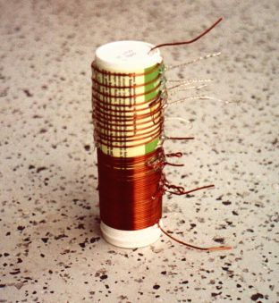
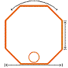
Fig.1: asymmetric series of capacitors (purple) terminating a magnetic loop

Pic.1: real life look of the terminating capacitance
Fig.2: Dimensions used for the 20m band, blueish stuff being RG213

Pic.2: this is more than half a meter of RG213 dangling out the loop
Speaking of dimensions (finally), I need to add that the loop conductor itself is made from precisely 4m of 14x2 PEx/Al/PEx (out diameter 14mm, wall thickness 2mm).

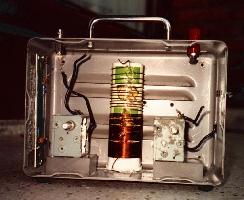
Of course, a magnetic loop aerial needs a primary loop:
Pic.3: primary loop
Dimensions for the primary have a thumb rule: 1/6 diameter of the radiator when placed very far from objects, 1/5 in average situations and 1/4 when used in doors. Mine is made from 80cm of copper installation wire, i.e. 1/5 diameter of the radiator. Of course is very easily exchanged when going indoors.


Why are those dimensions selected?
As to the loop diameter, having a loop with a generic resonance not much above the future operating frequency allow for small capacitance values to terminate (tune) the loop. Having a low terminating capacitance lower the voltage across the capacitor and broadens the bandwidth of the loop.
The length of 4m of said material, when bent into a circle, deliver a natural resonance at about 15.5MHz. Starting from there, very little capacitance is required to resonate the loop at 14MHz.
The 70cm for the length of the "insert" were a lucky scientific a precise guestimate...

How to tune this loop and why is it asymmetric in capacitance?
Both these question seem unrelated, but they are not! The beauty of this entire design is found in asymmetry actually. Remember the section about changing the larger or smaller capacitors in a series of capacitors? The shorter end of the coax (when inserted into the tubing) acts like a "band set", the longer end like a "fine tune".
Inserting the coax entirely in a symmetrical fashion, the resonance drops to close to 9MHz, tuning here is very fiddly...
Having the coax in asymmetric configuration, the longer end provides relatively smooth tuning.

What is the bandwidth?
Well, I have not yet tested the aerial decently, but, first measurements with an MFJ-269Pro indicated that the loop, tuned to 14.060MHz is good for +/- 20kHz.
Certainly there are ways to calculate the bandwidth, the radiator 12mm has a circumference of 4m. There must be some web-application to evaluate such a loop (http://www.66pacific.com/calculators/small_tx_loop_calc.aspx) indicating a bandwidth of about 40kHz... (see below).

My plans for the loop are: QRP and PSK on 20m. Hence, I taped down the short end, as to have my band set. Of course, WSPR and QRSS are also in the reach of this loop...
This loop still is in experimental stage. For a more permanent solution, I will install an electrical box over the terminating capacitor, as to prevent water to collect within the tubing. For the same reason I may even drill a small hole into the bottom of the loop, allowing for drainage.

Concerning the dimensions of such a loop, 30m may still be an option. However, I rather see myself building this loop for the higher bands in the near future.


Results from 66pacific.com:

RESULTS:
Antenna efficiency: 68% (-1.7 dB below 100%)
Antenna bandwidth: 40.3 kHz
Tuning Capacitance: 50 pF

Capacitor voltage: 631 volts RMS
Resonant circulating current: 2.77 A
Radiation resistance: 0.223 ohms
Loss Resistance: 0.104 ohms
Inductance: 2.58 microhenrys
Inductive Reactance: 228 ohms
Quality Factor (Q): 349
Distributed capacity: 11 pF

Antenna "circumference": 4 meters

Loop antenna Side length: 0.500 meters
Antenna diameter: 1.2 meters

Comments:
The specified conductor length of 4 meters is OK.

Conductor length should be between 2.59 and 5.17 meters at the specified frequency of 14.06 MHz.

For highest efficiency, the conductor length for a small transmitting loop antenna should be greater than 1/8 wavelength (greater than about 2.59 meters at the specified frequency of 14.06 MHz).

To avoid self-resonance, the conductor length for a small transmitting loop antenna should be less than 1/4 wavelength (less than about 5.17 meters at the specified frequency of 14.06 MHz).


Input Values:
Length of conductor: 4 meters
Diameter of conductor: 1.2 centimeters
Frequency: 14.06 MHz
Transmitter power: 5 watts

Sunday, March 30, 2014

3 Inch HiFi PVC Pipe - The Alphorn (MLTQWP)

Finally I found some time to tell/show a little bit more about the speaker enclosures I was bragging about so much lately.

Most importantly, why was this so interesting to be posted on a blog concerned with RF. Well, to my very own understanding, the principles behind emitting sound waves it somewhat similar to the principles of emitting radio waves.
Here is why:
Analogy between a quarter-wave vertical and a quarter-wave speaker enclosure
On the left hand side, the above sketch shows the good old vertical quarter-wave antenna driven by a gamma-match. Indicated in blue, the current distribution along the radiator. Of course, this current will emit a magnetic fields (green), which was the purpose of the antenna in the first place.

On the right hand side, you see a loudspeaker cabinet called quarter wave pipe (QWP). In such a pipe design, similar to the gamma-match of the vertical, a driver (in acoustics loudspeaker chassis are called drivers) creates pressure waves (green) somewhere in the middle of the "conductor". Similar to a quarter-wave antenna, the conductor is excited at a resonance frequency. The blue line indicates the air speed, i.e. current, through the pipe. The red arrows indicate sound emissions.
  • The driver emits sound to the front side of the cabinet.
  • The standing wave emits sound at the open end of the pipe.
While the driver emits what ever is present in the AF signal, the pipe predominantly emits sound at its resonant frequency and harmonics thereof. The latter, of course, is a problem! In musical terms, this could lead to a "One Bass Note Samba", something nobody would enjoy, contrary to the "One Note Samba" having quite some more notes than one only.
Consequently, the bandwidth of the pipe needs some severe broadening!

Back to aerials, there are 2 ways to make an antenna broadband:
  1. add more resonators (e.g. log-per, dipole fan)
  2. add Ohmic resistance (e.g. T2FD, Beverage antenna)
In acoustics, both can be done too. As I indicated before, antennas and speaker cabinets have a lot in common!
In acoustics, one can add more resonators by tapering a restrictive volume and add resistance by stuffing said volume with dampening material.

For a HiFi speaker cabinets one needs a very homogenous emission over several octaves, i.e. close to 0Hz up to 22kHz (those are, of course, extremes). A mixture of multiple resonances and some severe resistance is used. Actually, there is an added bonus on the resistive part of things... not only does stuffing material add resistance, it also lowers the velocity of sound within the medium. A stuffed enclosure looks larger to sound-waves than the same enclosure not being stuffed.

PVC piping, at last we leave the theory part of things, is a very convenient stuff to work with. Now we talk about pipe in the sense of water pipe. Have I forgotten to mention that the word pipe could have several interpretations, sewage pipe, water pipe, organ pipe, pipes of bagpipes, etc. OK, pipes, i.e. PVC pipes, fittings and stuff thereof. Here is the B.o.M:
PVC parts

The parts serve the following functions:
  • tubing form the pipe's body, obviously
  • the elbow is the resonator's "mouth", bending pressure waves towards the listener
  • the T-piece is to the driver
  • the reduction pieces will taper the resonator
  • and the end cap will be the end cap, i.e. terminating the resonator.
The elbow, T-connector and fat tube form the lower part of the pipe. This is all 3" piping. The length of the tube it 1m.
The upper part of the pipe is tapered down to 2" and 1.5" PVC tubing. The respective tubes have a length of 50cm each. Obviously, fittings add length to the final product.
Adding 1 additional diameter to the taper, will just add 1 more resonance (and its harmonics). Hmmm, "Two Not Bass Samba", really?!  No, that does not help!
The tubes therefore receive insets. The process of making those is pretty easy. My preferred method is using heating pipe insulation foam tubing. Cut in half, the stuff can be easily be cut diagonally. A result of this is tapering for pressure waves.
Tapering inserts

That's the tapering part dealt with... Those speakers are called TQWP.

However, before putting everything together, we need to address the resistive part of broadening the bandwidth of the pipe and lowering its resonance. There is no photo of this step. The material involved is polyester from an IKEA pillow, the cheapest acoustic stuffing on the market!
I complemented the inserts with the pillow stuffing and shoved it down the respective 50cm PVC tube.

We are nearly finished... there is just one other addition, before the "cabinet" can be assembled. In order to prevent the creations of unwanted harmonics, dampening material (cleaning cloth!) has to be added behind the driver (within the T-piece).

Here is a photo of the finished speaker:
The Alphorn speaker

Yeah, this is a very tall speaker. For obvious reasons, I call this speaker "Alphorn". The image above shows the thing from floor to ceiling, as installed in my attic.
The sound of those speakers is amazing! From classical to hiphop, via kizomba, funk and rock... the sound of those speakers blows me away!
Mind you, those are very cheap 3" drivers...

The drivers came in a stereo set priced less than €40.
Why am I mentioning this? The price for the PVC plumbing parts, used for this project, is actually > €42.The passive parts of the project exceed the price of the active ones... not sure what that means in the context of modern electronics.
Speaking money, the Alphorn speakers sound like speakers in excess of at least 1k€.

Back to theory... the total length of the pipe is about 225cm. 2,25m in quarter-wave reflects 9m of wavelength, which in itself equates to a sound frequency of about 33Hz. This would be the resonance of the empty (non-tapered) pipe.
As said before, the upper part of the pipe is stuffed with IKEA pillow material, hence the real resonance frequency will be even lower. Stuffing enclosures is called "Mass Loading".

There are 2 sharp steps in the taper, one at 120cm and one at 175cm. Those steps add resonances at 62.5Hz and 43Hz, which of course will also have harmonics too.

The resulting speaker enclosures qualify for the MLTQWP... and... they sound amazing!

UPDATE on alternative design thoughts. Thoughts only. On the internet a couple of designs float showing curved structures, involving a plurality of bends and elbows. Similarly to stepped tapers, those bents create reflections and disturb the air-column of the standing wave pretty good. Bending the design to limit height of the speakers seems however a very attractive thing to do.
My gut feeling tells me that 45º bents at carefully selected lengths could work. Maybe two of those just above the feeding T, followed by a reducer and two more 45º bents. Such a design would keep the tallness of the speaker at about 140cm. However, I still believe that such a measure will reduce the amplitudes of the lowest frequencies.


Monday, March 17, 2014

More Pipiness in the Audio Department

More improvement to report on the PVC pipe speaker enclosures (Voigt pipes).

Today I decided to stuff the upper pipe resonator. Stuffing reduces the velocity of sound due to increased density of the resonance volume. Such an increase of density lets the resonant volume appear larger to the sound-waves.
Quick excursion to a previous post: those pipe-enclosures are just broadband quart-wave resonators, having a pressure node at the closed end of the pipe and a velocity node at the open end.
Reducing the velocity of sound inside the pipe will therefore lower the quarter-wave resonance, resulting in more bass.

Poor man's stuffing could be cotton wool (cotton batting). This stuff introduces a severe problem! The pipes will be home of moths!

There is help, however, a real poor man's stuffing: polyester fiber from real cheap cushions. At a modern Swedish furniture store, such cushions are as cheap as €2/pc containing 400g of fibers, which is a lot more than needed.

I loosened up the cushion fiber, in order to create a very light and fluffy stuffing. Mind you, with 2" drivers, you don't want to dampen too much. It took just a few grams to lightly stuff the tapered resonators.
The result was quite pleasing. However, running the converters w/o the upper resonator revealed some adverse effects of the horn (lower part of the pipe/resonator).
To remedy this effect, I dropped a quarter cleaning cloth, cut the long side, into the tube, covering the back of the driver and following down as deep as possible.

Finally, my PVC-plumbing Voigt pipes are pretty close to Voigt pipes made from wood, as found on the world-wide-waiting-network, i.e. stuffing above the driver, damping behind the drivers and a horn like bass mouth.

As announced before, the next step has to be the homebrew low noise amp.


Thursday, March 13, 2014

PVC Pipe Nightmares

Uhh?! What is going, first he told us how cool those pipe are, and now nightmares?! What is going on?!
Very simple, when pushing one inferior variable to the best possible, another one will take the place of being the disturbing one... the one that spoils all the fun and excitement.
Well, this time, it was the stereo that was driving the fun, as I thought.
Although I still believe this is a very nice device, I have to report that this device creates a hizzzzzz under "normal"circumstances. As soon as any of the buttons is tampered with, the hizzz is absent, just to return after a few seconds... VERY ANNOYING!

This "feature" was audible only with my PVC Voigt pipe-type speakers. What do we learn from this?!
  • When using a cheap stereo, use the speakers supplied, so you don't hear the deficiencies!
  • When hooking up a cheap stereo to some decent sound converters, you may be able to hear the defects the respective sound converter has.
  • Dimensions given by your sound-Guru are relative... does a 1.5m Voigt pipe sound better than a 2+m Voigt pipe?! Probably not... shorter pipe, less bass..
Am I happy with my more than 2m long Voigt pipes driven by 2" drivers? Yes I am! I think those are the most amazing cheap speakers I ever listened to!

Remedy for the hizzzzzz problem: build a dedicated AMP (opamps/LM368) in a classical way...


Wednesday, March 12, 2014

Pipe Dreams X(X)L

Guess what, I am still experimenting with sound reproduction, HiFi audio that this. And of course, I am still on the cheap, sort of.
In my previous pipe dreams post, I discussed improvements of a stuffed transmission line made from PVC pipe. I still like the results, however, there is some bass missing... Depending on the genre to listen to, this is fine, however, lets assume the bass is really needed in a certain presence.

There was a certain Mr Paul G.A.H.Voigt, who is a simple speaker design named after. The Voigt pipe. And indeed, this design in a pipe, the like pipe of an organ. Actually a bass pipe, a broadband bass pipe.

The interested thing about such pipes is that they work similarly to what we know as "gamma match" in radio. At a certain fraction of the length of the pipe, a standing wave is created. While in a aerial, the current at 0 Ohms determines the radiation. In an audio speaker, the open end (zero resistance) aka mouth, does the same thing. As in aerial design, speakers have near and a far field responses.

Here I am, running a "gamma match" speaker, i.e. a speaker that functions as a pipe of an organ.
An organ pipe, of course, resonates at exactly one frequency. This is not ideal, unless playin' the "One Note Samba" by A.C. Jobim at the resonance frequency.
When using RF dipoles having (slightly) different resonance frequencies, the bandwidth of the antenna system can be widened easily (cf. log-pers and dipole stacks). 
Also, added Ohmic, i.e. lossy, resistance does a trick of broadening the resonance (cf. T2FD).
Pressure waves in sound follow the exact same principles. Instead of a dipole array, a resonating body is tapered. Instead of adding Ohmic resistance, damping material is added.

Here is a difference:
  • In radio, we want to transmit on one particular frequency. Any other frequency, we want to suppress as much as possible (unless running wide spread spectrum, that is).
  • In HiFi audio, we want to emit the entire spectrum as evenly as possible, the flatter the better!

However, there is a problem in HiFi audio with deep frequencies (long wavelengths). Pressure of such wave seems to collect in upper corners of rooms having a finite size, creating unpleasant rumble/mumble. So, the question is, how low do we need/want to go?! In a workshop about studio acoustics a once learned that studio monitors smaller than 5 inches are better suited, since those don't create said deep bass frequencies being so disturbing.


So, let's see what we have... 2 inch scrap speakers (salvaged from a dead small flat screen TV) as full range drivers.
In the precious posts, you see how those did in a damped 1m TL PVC pipe setup.

Same divers, similar back horn setup (removed all damping material from the back horn). Well, actually, there is no real back horn any longer. What used to be the back horn is now part of a pipe.
PVC Voigt pipe
The elbow containing the driver is replace to a T-piece. The upper part of the T-piece is connected to a reducer piece, which reduces the pipe diameter of 32mm.
The length of the closed 32mm pipe is 1m.
A Voigt pipe is not only closed, in order to create a standing wave (to the mouth), but also tapered, in order to widen the bandwidth. In my setup, I decided to taper the pipe by adding a angled cut of a cult in half insulation foam pipe, which I was writing about before.
Here a photo of the such a cut in half foam pipe.
imagine this diagonally cut in half, creating 2 similarly tapered pieces
Such foam is inserted in the upper (closed) end of the tubing, creating a tapered resonant body (stacked dipoles).
The lower half of the upper pipe's tubing is stuffed with 1/8-ths of a cleaning cloth, in order to reduce further reduce resonances (Ohmic part of the game).

To further improve sound response, some damping material was added behind driver. Care should be taken not to reduce the volume the driver breathe from.

Up to now, I played with 2 inch drivers only, there are drivers of greater diameter in my scrap box.

=> Stay tuned for more speaker madness!

Sunday, March 9, 2014

PVC Pipe Dreams (audio)

You have seen speaker enclosures I made from PVC plumbing pipes. For stuffing the pipes, I initially used heat pipe insulation (the grey stuff in the image below). It worked OK, at least to an extend I was surprised, concerning those tiny drivers.

speaker stuffing material

I experimented a bit with household cleaning cloth, as shown in the image... the stuff you would clean for bathroom with. The stuff was on sale, €1,- for 2 sheets.
What the hack, I rolled one up and stuffed it in the speaker pipe. Clearly, the mouth of the pipe now only did "mmmm mm mmmmm" (referring to very deep bass notes). The all over volume of the speaker went way down. I guess, I restricted cone motion quite a bit with that much mass.

This stuffing:
  • 0.5m of the insulation stuff
  • 1/4 sheet of rolled up cleaning cloth
was the next experiment.
Now the driver has got nearly half a meter of pure air column to breathe, followed by the insulation foam and some loose stuffing of soft cloth.
In a way, this is like tapered increase of acoustic density.

Again, the result is really interesting, seen the small / cheap drivers. Of course, you would not expect a hammering deep bass.

Still more to experiment, I pushed the cloth stuffing about half way into the PVC tube. This way, I think, the driver has to some volume to breathe from and the longer wavelengths, that made it through the stuffing, can form more homogeneous pressure fronts, before exiting the enclosure.
Again, some improvement could be noticed.

Speaker enclosures, made from PVC piping, seem to offer endless opportunities to experiment.

Monday, March 3, 2014

PVC Pipe Speakers

Yep, I know, this is not RF, this is AF. However, this post my be of interest anyways.

Recently, my first ever LC-Television died on me. Of course, the device had to be source of parts. And it was! The sound of this TV was not bad, hence, I also took the 2 tiny 2" full range speakers out before I crapped the rest.

After collecting some dust, the chassis are finally put into operation again, wit the help of 2" (55mm) PVC pipes.

The speakers are house in elbows, taped in by electricians tape:

the driver

Followed by 1m of 55mm PVC pipe, providing the air column. The pipe is actually filled with a "pipe insulation jacket" as to reduce resonance effects and also increase the acoustic resistance.


the speaker box


Of course you would not expect the sound of a Klipschorn from this device, however, you will be surprised how much bass a 2 inch speaker can deliver, being placed in a decent enclosure.
I am sure that sound quality can be improved by stuffing the tube properly, however, the foam tube insulation was just so tempting to do, cheap and easy, and it works surprisingly well.

Saturday, February 1, 2014

PE-Xc/Al/PE-Xc aka PEx/Al/PEx the New Copper?

Wanting to build a low profile mono-band antenna, I looked into the old design by J.M. Boyer (U.S. Patent 3,151,328). The DDRR-antenna, as originally designed, i.e. about a quarter wave circumference, allegedly as a rather narrow bandwidth.
There is another variant out there, which is said to got a wider bandwidth. This design asks for a half wave circumference, which the advantage of having a closed loop (less noise!) and no need for an expensive capacitor.

OK, that's a plan, let's think of a DDRR for my flat root top. This antenna would be entirely invisible from the street.
But, what about the B.o.M. (Bill of Materials)? Well, a neat design would call for about 21.34m of soft copper tubing having a 10mm diameter. Well, the stuff exists, however, however, a 25m roll of 12mm soft copper tubing would cost about €185.- presently. Well... that's a bit too stiff or my taste!

The hardware store had also 5m rolls of 12mm copper tubing for about €30.
OK, we are coming closer, I would need to buy 2 such rolls and an additional piece of piping, in order to build a quarter wave DDRR antenna. But, I would need to think of a (variable) capacitor.
Nothing of interest, I decided, and left this particular store.

Next store, maybe their copper prices are lower... no, there were not! However, I noticed some other stuff, which the first store did not sell. The stuff is called PE-Xc/Al/PE-Xc, aka PEx/Al/PEx.
What is that?!
  • PE-Xc or PEx stands for "cross-linked Poly-Ethylene"
Hugh, you might think, is he gone crazy? Building an antenna from PET, the stuff of which fizzy drink bottles are made of?
Well, there is this other material in the and ....
  • Al stands for Aluminium (Aluminum)
The PE-Xc/Al/PE-Xc-stuff is a tubing material made from an Aluminium layer sandwiched between 2 poly-ethylene layers. The interesting bit about this Aluminium layer is that it is supposed to be an Oxygen barrier (cf. wiki) and is therefore sealed by welding (according to many manufacturers).
14mm PE-Xc/Al/PE-Xc
Right, now we know that the PEx/Al/PEx stuff can be interesting for building antennae.

Also good to know, the stuff is very lightweight, compared to Copper tubing. Not only is Aluminium one of the lighter materials, the Poly-Ethylene makes the stuff really tough (10bar of pressure at 95C), such that the metal layer can be much thinner. Mind you, in radio frequency, we are only interested in the most outer diameter of the metal, thanks to the skin-effect.

The price? Alright, time to talk money. I bought a 10m roll of 14mm PEx/Al/PEx for just under €30. Only half the price of Cu-tubing?! Is that worth it? Well, the costs are not hidden in the materials for PEx/Al/PEx, since, a 10m roll of 20mm tubing, the largest diameter this particular store had in stick, is only €35.

Enough about the material itself, you'll find plenty of information about it on the interweb!

A material so light-weight and still stiff calls for designs like hair-needle antennae and alike.

Pretty novel, I thought... NO it is not! There is one design disclosed in the interweb, which makes use of PEx/Al/PEx in a magnetic loop / frame antenna cross-over. Have a look at the "2 TURN LOOP ANTENNA".
What I like about this design is that no electrical connection is made to the Aluminium layer. Why? Aluminium is not exactly a noble metal. Any connection with a metal other than Aluminium may cause problems, one or the other way.

Along those lines, how would one possible connect a capacitor to the Al-layer? Well, that is, considered the dimensions, actually pretty simple. Have a look at the images below, they may look disturbing. And yes, this is pretty ghetto!
RG-213 meats PE-Xc/Al/PE-Xc

close up
And here is where the capacitor resides, between the Al-layer of the PEx-Al tubing and the braid of the RG-213. Of course, the braid of the 213 is made from Copper, however, the is no Galvanic connection between those metals, and hence, no corrosion!
Although the RG-213 fits into the PEx-Al tubing nicely, there is some friction... and that is good!


Ideas
  1. Building a magnetic loop from the materials shown above.
    A single turn loop made from PEx-Al with a length of RG-213 inserted into both ends of the loop symmetrically. The loop will be tuned by widen or closing it other the inserted length of RG-213, actually acting like a butterfly-capacitor. I will aim for about 14.070MHz. Once tuned, I will tape up the loop endings in order to lock tuning and prevent moisture to enter into the tubing.
  2. Building a quarter wave DDRR, as intended in the first place.
    Similarly to the magnetic loop above, the capacitor will be formed by RG-213 inserted into the PEx/Al tubing. However, there is a problem with the ground connection of the loop! The present idea is to remove the outer PE layer, wrap the Al-layer with Al-foil and clamp this down with a hose clamp. Of course, the Al-foil will corrode, hence, it will have to be replace occasionally.
  3. Building a frame antenna.
    This essentially means to coil up a good part of the PEx/Al to a decent pack, having a coupling toroid in the center winding. This technique, you might have seen at various antennae I published before, e.g. OctaPlumb (different plumbing material though).
  4. Different PEx/Al tubings might fit into one-another, forming capacitive couplings.
  5. I can imagine using PEx/Al with INOX-screws connecting various coils thereby, together with capacitors as disclosed above, forming traps.
  6. The PEx/Al tubing might potentially be usable for shielding a loop made from RG-213. Insert theRG-213 into the tubing, both end peaking out. Solder things down at the "far end" of the loop and slide the far end to the tubing... Follow your imagination for the rest!
Conclusions
First, I had in mind building a DDRR-antenna. However, seen the possible simplicity, I may build a magnetic loop first.

Post Scriptum
It seems that the PE-Xc/Al/PE-Xc, best suitable for amateur radio, is found under "floor heating".


Wednesday, January 29, 2014

Update: Flower Pot Heater

The last few days, I experimented a bit with the flower pot heater... actually, I turned the one heater into two! All experiments were done whilst my central heating was set to "frost protection".

From a physics point of view, the 4 pots, as shown in the previous post, are a rather large thermal mass. And of course, physics does not lie. Despite the 4 candles, it took some time to build up noticeable radiant heat, which than lasted for quite a while. In this respect, the 4 pot solution is more of a constant heater than an "on demand" device.

At some stage, I removed one inner pot and tried with 3 pots bolted together. This has proven to be a little bit faster in heating up, satisfactory it was not. The mass of the big pot takes too long to warm up appearently.

The next experiment was to use the second to largest pot and the 2 smaller ones. I also removed the brick at the opposite end, since I noticed that the candles were not getting enough oxygen. Well, some improvement, but still not really up to scratch.

In the next iteration of experiments, I used only 2 pots, the smallest and the second to largest. Also, I reduced the amount of metal inside by using a shorter bolt. The reduced circumference of the setup allows for a smaller soucer to hold the candles. The bricks set flat now, the distance between the flame(s) and the thermal mass is reduced, speeding up the warm-up. Noticeable difference!
Some remark here, it seems that in particular when using more than 2 tealight candles, the soucer I used was filled up with cold CO2 so quickly that one candle always fainted. It seem that the heat-transfer is very effective, so effective that the CO2 fall straight down on the candle(s). When the setup is warmed up a bit, this effect is gone.

Radiant heat is kinda cool (warm that is), however, what about heating air? And yes, this works well, however, it slows down everything again. What works well, you may ask...
I used 4 candles in the 2 pot heater mentioned above and placed the big flower pot on top. Since this time the big pot is not connected to the bolt, the hole in the pot is open. Heat builds up between the bolted 2 pot setup and the outer loose pot, which due to the chimney effect is drawn upwards through the big pots hole. In the course of time, also the big pot heats up such that it radiates heat.
Such a setup creates heat by convection and at some later stage also radiant heat.

Latest experiment: two 2 pot heaters.
I believe you understand where I am going from here. The big pot was loose already, and the second to smallest was not used at all.
Some considerations about the 2 heaters I have presently available. The biggest pot will have a large thermal mass, which stores heat for a while. The smaller pots (less mass) will heat up fast and start radiating relatively quickly.
Since a couple of days I experimented successfully with the following scenario. The smaller heater is in my study, where I do stuff in the late afternoon, just when I returned to home. This room needs quick heating, so I use the smaller FP-heater with 2 or 3 TL-candles, to get radiant heating asap. At the same time, I would light a single TL-candle in the big pot heater to create a certain baseline warmth in my bedroom. Halfways into the evening/night, I might have to replace this single TL-candle with a fresh one. The big pot does not get very, it is warm to the touch at the top and cold at the lower side, however, my bedroom feels just right with this amount of heating.

Again, this is not radio related... sorry for that! However, I believe that this could be of some interest to some of my audience.
2 tealight candles per night to keep your bedroom comfortable... how cool (ergh warm) is that?!

BTW: There are some critics writing rather negatively about this particular way of warming a room. And honestly said, they have point!
We, including me, are talking about "heaters". Of course this evokes the impression that those things are really hot, creating a lot of "heat", litereally. But than, those devices are not up to such expecations for very simple reasons. Here is one: tealight candles are designed to keep a pot a tea warm for some while... that's all! The idea is not to create an amount of heat so that the tea will evaporate in a couple of minutes. So, should we expect the very same candle to be as hot as a Bunsen-burner?! It is the constant flow of a small amount of energy that keeps your bedroom cosy... not more than that!

Saturday, January 18, 2014

The E-Probe Got a New Location

The regular reader of this blog may know, that I am using different aerials for my grabber. All on a longer term. First it was the DCTL, than it was the E-probe (aka. modified mini-whip).

For many months, the E-probe was just dangling from the edge of my upper roof, which screened South by a good part.

Since some weeks, I put it on my upper roof. As soon as it was up, of course we had a solar storm and condx went down. Even with condx up again, not a single DX was received. I figure this would be caused by the rather low position of the E-probe. Reason for that decision was to be safe in storm. It can actually blow a bit here in South Holland.

Here is how this setup looked:
E-probe, just above the edges of the roof


Today, I decided to raise the E-probe by 1m, by adding an additional piece of PVC pipe to the construction. Originally, I wanted to use a straight coupling piece to do that, but that would have meant to pay a visit to the hardware store. In garage, where I kept the piping, I found a matching T-coupler. This could be used to the advantage of the setup!
Why not feeding the coax-cable through the stand, a guide it out at the T-coupler?

Of course, first I had to take thing apart, in order to feed the coax through the stand's tubing.
Disconnected and in pieces
DONE!
Now to the first impressions. Of course I did not shutdown the grabber during the process, so one can see a clear "before and after" (and also some in-between).
Before
During (and after)
After
 What happend? (times in Zulu/UTC)
  • 13:26 - I disconnected the coax from the E-probe
  • 13:30 - reconnected the coax and arranged stuff
  • 13:33 to 13:34 - cleaning of the BNC-connector 
  • 13:34 - I left the roof
My first impression is, that I am able to receive 3 QRSS stations, just minutes before, I did not receive any. 

I just hope that the leverage of the higher E-probe will not cause the entire thing to be blown off the roof by the next breeze.

Update:
The relatively lightweight bricks are now replaced by heavy concrete garden tiles. This should do, even when storms should come up.
The bricks will now be used for another flower pot heater...

Friday, January 10, 2014

How to Create IR Radiation on the Cheap

Before you continue reading, this is entirely off-topic, really! You might have heard about the hype of "flower pot heaters", which is all over the internet, in particular youtube. Well, this is my attempt on building one.


Usually, when a candle burns, the hot combustion products just go up to the ceiling, where the heat is than disposed. Very useful indeed.
If you have ever been to a room full of candles, you will certainly remember that such a room get quite hot after a while. If you have never experienced this, there is a nice scene in the German comedy movie "Rossini".

The basic idea of the "flower pot heater" is to catch and store the heat of (a) candle(s) in a thermal mass. The problem with candle exhaust is of course that it goes straight up, to catch it, one needs some cloche shaped thermal mass.
Of course, at some stage, hot gases will have filled the cloche. At that stage, said gases will spill over and reach for the ceiling, which is undesirable (see above).
So, lets put a larger cloche above the first one, and than another, and another, and another ..... well, we have to stop somewhere.

I went for 4 raw terracotta flower pots. Terracotta is a pretty nice material, since it is rather heat resistant having been burnt before (terra cotta = baked earth). There are glazed pots available, avoid those, the glazing will reflect IR radiation rather than absorbing it. Yes, we also want the IR and vis. radiation of the burning candle(s).
The pots, cascaded as a matryoshka doll, are held together by a steel bolt (with a flat head for better looks). Distance is kept by washers and bigger bore nuts.

When assembling the stack of pots, you want to make sure to have some spacing between the pots. Also, whenever touching a terracotta surface, you want to use a washer.

Have a look at my matryoshka doll:


Flower Pot Heater - the Radiator

Concerning the stand, there are wild ideas out on the internet. Mind you, the radiator is a mass, in terms of physics, this also means it weighs! In operation, the relatively heavy will be hot... and due to the nature of its materials, it is also relatively fragile. You don't want any of this tip over of fall, or whatever... in particular with burning candles around.
A very popular stand is a baking form. This is a very unstable solution, the baking form has even got rounded edges around the bottom, as to release bread easily. Please do not even consider using this solution!
Here is mine: a solid plant stand carrying a glazed terracotta saucer and three building bricks.

Flower Pot Heater - the Stand
For the "base" of the burner, you actually want to have the saucer to be glazed. This helps reflecting heat up into the radiator.


Everything put together:

Flower Pot Heater - Ready for Action

To test the heater, I switched my central heating system to "frost protection" (i.e. 5°C) at a room temperature of 16.5°C. The heater than was lit with only 1 tea light at 3pm. Additional 3 tea light were installed at around 7pm. At about 8pm, the first tea light burnt down, the room temperature being 18°C. It needs to be said that my living room is rather large, for Dutch standards, and attaches to an open kitchen.

Wisdom of the internet reveals that one tea light generates heat at a rate of about 80W per hour.

In addition to the heat, the contraption acts like a mini fireplace, giving a rather cozy feel to the room, when electric lights are down.

PLEASE, don't burn down your place! I wont sign responsible.

update: About 1:00, the remaining candles went down, the temp still being 18°C. However, the temperature dropped by half a degree centigrade, half an hour later.

Up to now, I am very pleased by the results, I will experiment further.
Mind you, you can buy 100 tea-lights for about €2,50.

Update:
I removed the outer pot. This one was really very massive. OK, it kept the heat for quite a while, but took aged to heat it in the first place. This modification also made in possible to lay the bricks down, allowing for the inner pot (and the metal) to be closer to the flames. Obviously, the saucer is replaced by a smaller one.

2nd Update:
Still, for my taste, the heat was deployed to slowly with just 3 pots. Hence, today (19.01.2014), I removed the middle pot of the remaining 3 pots. Mind you, the size of the inner and the middle are really close to one another.
This the middle pot removed, keeping all the metal in side, the outer pot gets hotter in a shorter time. It seems obvious that the heat retained in the present setup will last shorter, since mass was removed. However, the 2 pot setup, with a lot or steel in the core, seems to behave much more like a heater.
I figure I have found my setup. Will update further, with dimensions, whenever I feel alike. Stay tuned!

Saturday, January 4, 2014

20m MEPT

20m FSK-QRSS MEPT

This is a very rough and rudimentary version of a 20m MEPT. It worked, but it is supposed to be a starting point only!

Initial design


First revision


Superhet XTAL Combinations

The following list is rather old, however, it wont be outdated as long as we keep out frequency bands.


Crystals for QRP and homebrew


The presented lowcost standart crystal frequencies are selected for the usage in superheterodyne sideband transceivers (receivers). For extension to this list, look at 7N3WVM's homepage. Makoto, in addition to his list, shows a block diagram for superhets, and provides excellent information about VXOs. The frequencies in this list need in some cases multiplification with a given factor M. The intermediate frequency if is shown for superhet designs. Crystals for the intermediate frequency have to be fundametals for easy to build SSB/CW ladder filters. Where the frequency multiplication factor equals 1 you might swap VXO and filter frequencies, depending on your junk-box/requirements.


HAM band  VXO [MHz] M if [MHz] QRG [MHz]
         
160m 9.8304 1 8.000 1.830
         
80m  6.000 1 2.4576 3.542
  6.400 1 2.4576 3.942 (*)
  8.000  1 4.4336 3.566
  8.000  1 4.500 3.500
  8.867238  1 5.0688 3.798
  9.8304 1 6.000 3.830 (*)
  9.8304 1 6.144 3.686
  10.000 1 6.400 3.600
  11.000 1 7.3278 3.627
  11.0592 1 7.3278 3.686

12.75
1
9.216
3.534
 
14.7456 1 11.000 3.746
  22.1184 1 18.4321 3.686
         
40m 4.000 1 3.2768 7.277 (*)

4.9152 1 2.097152 7.012
  4.608 1 2.4576 7.066
  5.0688 1 2.000 7.069
  11.059 1 4.000 7.059 (++)
  12.000 1 4.91403 7.086
  17.73447 1 10.700 7.035
  22.1184 1 15.000 7.118
         
30m 6.5536 1 3.579545 10.133
  6.144 1 4.000 10.144
  7.3729 2 4.608 10.138
  7.3729 3 12.000 10.118
  14.31818 1 4.194304 10.124 (+)
  14.7456 1 4.608 10.138
  22.1184 1 12.000 10.118
         
20m  6.400  5 17.73447  14.265 (?)
  9.8304 1 4.194304 14.025 (+)
  6.5536 5 18.432 14.336
  8.000 1 6.144 14.144
  9.216 1 4.9152 14.131
  9.216 1 5.000 14.216
  9.000 1 5.0688 14.0688
  9.005 (**) 1 5.0688 14.074
  9.216 1 5.0688 14.285
  9.216 1 5.120 14.336 (+++)
  9.8304 1 4.4336 14.263
  10.000 1 4.000 14.000
  10.000 1 4.096 14.096
  10.000 1 4.194304 14.194 (+)
  11.000 1 3.2768 14.277
  9.216 1 4.9152 14.131
  11.0592 1 3.2768 14.336
  16.000 1 1.8432 14.157
  17.73447 1 3.579545 14.155
  22.1184 1 8.000 14.118
  24.000 1 9.8304 14.170
         
17m 12.000 1 6.144 18.144
  14.000 1 4.096 18.096
  22.000 1 3.9321 18.068
  22.1184 1 4.000 18.118
         
15m  6.400  5 10.700 21.300
  6.5536 2 8.000 21.107
  8.000 2 5.0688 21.069
  16.000 1 5.0688 21.069
  6.5536 4 5.0688 21.146
  7.3728  2 6.5536 21.298
  14.31818  2 7.3728 21.264
  14.7456 1 6.400 21.146
  14.7456 1 6.5536 21.299
  25.000 1 3.9321 21.068
  25.000 1 3.6864 21.313
  15.360 1 6.000 21.360 (+++)
  25.000 1 3.579646 21.420
         
12m  10.000  2 4.9152 24.915
  30.000 1 5.0688 24.931
  20.000 1 4.9152 24.915
         
10m  6.144 5 2.4576 28.262
  6.144 3 9.8304 28.262
  6.144 3 10.000 28.432
  6.5536 2 15.360 28.465
  6.400 3 8.867238 28.067
  6.400 3 9.216 28.416
  6.5526 3 8.867238 28.538
  6.5526 5 4.433619 28.334
  22.1184 1 6.000 28.118
  16.384 1 12.000 28.384
         
6m  8.867238 5 6.144 50.479
  9.216 5 5.0688 51.149
  9.216 6 5.0688 50.227
  9.216 6 5.000 50.296
  9.216 6 4.9152 50.381
  14.7456 4 8.867238 50.115
  18.432 3 5.0688 50.227
  18.432 3 5.000 50.296
  18.432 3 4.9152 50.381
  60.000 1 9.216 50.784
  60.000 1 8.867 51.133
  60.000 1 9.8304 50.170
  14.000
2 22.1184 50.118

     
2m 14.000 10 4.000 144.000
  14.000 10 4.096 144.096
  14.000 10 4.194 144.194 (+)
  9.216 15 6.000 144.240
  9.216 15 6.144 144.384
  17.73447 8 2.4576 144.333
  8.867238 16 2.4576 144.333
  14.7456 10 3.2768 144.179
(*) not for IARU region 1
(**) CB-crystal 27.015 MHz
(+) here is a mixer xtal available at 4.194812 MHz
(++) combination found by Juanjo - EC5ACA
(+++) combination found by Klaas - PE1MJZ
(?) questionable, intermediate frequency rather high

This list cannot be complete, and it is not claimed to be complete. If you feel the wish to respond, add new xtal-pairs, or send donations ... please do not hesitate to do so. But, remember that those crystals should be really inexpensive.

QRP Transmatch ATU

A QRP Transmatch ATU


Introduction

In regard of my contemporary personal situation, I decided to do something reasonable to come to new thoughts... Despite the title, this following device is not for qrp use only, as my experience soon proved. It was possible to match a 2m vertical wire at 80m with no sparks occuring up to 50W RF. But... on air experiences will show up later...

Circuit diagram

First approach, the ultimate transmatch
 
ultimate transmatch

Next try, the SPC transmatch
 
SPC transmatch


Circuit description

For theoretical background I would like to point the reader to the common standart literature as the famous RF textbook of Meincke and Gundlach, or comparable other readings. The first approach was thought as an experiment to understand the so called ultimate transmatch (UT, first proposed by Lew McCoy). In principle I would recommend this design, also driven by my practical experience. It delivers good matching with moderate bandwidths. Besides that this design might have a slightly higher loss.
Apart from what I have written in the first version of this text, all the parts were fine to build a UT-ATU, but the rotary switch, and my attention at this time, fooled me. Thinking I got a 1x12 switch, I soldered the wires fitting this type. A few days later, reading a catalogue, it was clear, that the built in think is a 2x6 type. An additional switch cured the "problem". So, the finally completed ATU now is an UT.
Advantages: very smooth tuning even at the more critical frequencies like 29.690MHz, our local (Hamburg, Germany) repeater. QRO in this design seems not to be harmful at all, 120W RF on all available bands (40m to 10m) were matched to a 2m wire as well as to a 10m wire w/o sparkling ATU ;-)
As a comparison, I chose the series-parallel capacitance transmatch (SPC), for the reason that it took me just two leads reconfigured to convert on to another. Formerly I also planned to test the standart transmatch, but the overwhelming wish to get on air forced me to stay at the simple - to - obtain - by - the - most - simple - modification - design (smiley!). Disadvantages in this design (agn, have a glance to the textbooks) are the extreme narrow bandwidths and the low QRO ability (high Q).
What to chose if money plays no role? Certainly I would go for the UT, with two two-gang vernier capacitors at 1nF max (in both sections) and a roller inductor... if... but... it's all built from the junk-box.


Parts descriptions

The capacitors are the simple part. I just found them on the bottom of my junk box. They look like they were intended to go into AM broadcast receivers. In either design one has both sections wired in parallel. The inductor, the tricky thing in matching units with variable inductance. For the body I found an old pill container with a diameter of 4cm. The coil is then wound on this with 60 windings of 1mm enameled copper wire. The first 36 windings tight together, the rest with increasing wire to wire distances to the upper (hot) end of the coil. Tabbings are located at the windings 19, 28, 37, 42, 47, 50, 53, 55, 57, 58 and 59 for use with a 12 positions rotary switch shortening to ground, as I thought... In reality it's a 2x6 with an additional switch.

SWR indicator

My good friend Rico (DF2CK) had the heart to donate a PCB reflectometer to me. To make one yourself, have a look at Harry's (SM0VPO) Homebrew Page. Can't remember the way Harry did the rest, I added a 47k potentiometer for sensitivity adjustment, and a 4k7 suppression resistor to the forward meter, for reasonable reading during the tuning process. The meter itself is a standart stereo VU-meter, found in obsolete tape recorders (other superb parts could be found there likewise). Usage: Highest sensitivity and lowest reasonable RF power to start with. During the tuning you certainly will increase the RF power the closer you are to good matching. With CW, your favoured mode ;-), you then automaticaly will have the correct sensitivity setting during QSOs. For SSB contacts, you should keep in mind to reduce the sensitivity close to zero after tuning. The clicking meters will remember you to do so elsewise. Weak nerves would make you think of a sparkling capacitor, hi!

Tuning procedure

Yes, I know, that's common knowledge... but... we have two designs in this report. My experience was that the both designs have a contrary behaviour. Tuning with the UT: Fiddle during RX with all the buttons to get the loudest noise. You're allready close! Next is done with a little RF applied, power depending on the band, little fine tuning, done! QSO! Tuning mainly was done during RX. On the other hand I experienced that the RX maximum must not be the minimum in SWR.
Tuning with the SPC transmatch: More difficult, because of the narrow bandwidths. Set your transmitter to a few tens of milliwatts to find a C-L-C combination where the reflected power is halfways acceptable. Now the game begins! By slightly in/de-creasing certain capacities and inductivities find a good match. You will notice, it's much more complicated to find a good match, as the SPC transmatch with the given parts will provide exactly one for a specific aerial<->QRG combination.

Experiences

Clearly the SPC transmatch easily is able to match a 2m wire to 3.5Mhz w/o any problem, but, whatever band you're QRV on, watch the reflected power... Using the SPC transmatch, you will have to retune every tens of kHz. The UT give, as mentioned above, broader bandwidths. With both designs it now is possible to match a 2m wire to all bands (even 160m, although this makes no sense at all). It was easy to confirm the statements given in the literature about the behaviour of the presented matching networks. So, before you start soldering, think about what kind of aerial you want to match, and have a closer look to the textbooks. The opinion given there is that the UT can better handle inductive loads while the SPC transmatch is performing smoother on capacitive loads.

Photographs

The inductor. I know, does not look extremely professional...
Inductor photo

Box, partially assembled. The capacitors are glued to PVC insulators (using hotglue). Also the pill container inductor is glued to the box. On the left side, you can see the reflectometer PCB.
open box

Box, completed. The knobs for the capacitors nowadays are replaced by larger ones, depending on the settings your hand has a strong influence to the capacities.
transmatch in a box